Purpose of the CI-V interface
Any CAT (computer aided transceiver) system exists to provide a means to share data and allow remote control of a radio. Data is shared either with another radio or a peripheral device (i.e. an amplifier) or a computer. Data can be anything from frequency to operating mode, filter setting etc. Remote control can be any function of the radio, from keying the PTT to manipulating memory contents and any other settings.
The Icom CI-V system allows all this. From a historical point of view, the initial implementation with a single wire bus is extremely simple and easy to use when connecting multiple radios or peripherals.
The physical CI-V interface
The CI-V interface is in use since many years, at least since the 1980s. The physical interface has evolved from a 5V TTL level, single-wire line (bus) over RS-232 to USB, Bleutooth and Ethernet/Wifi.
TTL Level single-wire line (‘Remote’)
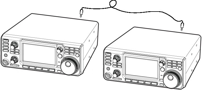
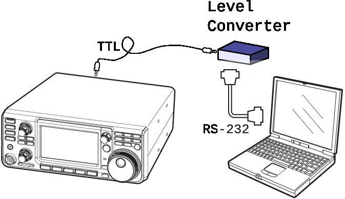
The oldest interface uses a single wire as an open collector line to connect several devices on a bus. The number of rigs on a line is not limited in principle, but by the “fan-out” (the driving power) of the units. Icom recommends max. 4 units on a single line. No specifications are made for max. length of the wire, but tests have shown that several meters will work fine with a good and shielded cable. The physical connector is a 3.5mm mono phone socket, labeled ‘Remote’. Shield is ground, tip is signal. You can use a stereo plug as well, just connect the ring to ground or leave it open. This simple interface allows to connect two radios or a radio and an amplifier directly, with just a simple and cheap cable. The connection to a serial port on a computer requires an interface, see ‘CI-V level converters’.
A few receivers like the IC-R20 use a 3.5mm stereo connector, where tip is audio, ring is CI-V data and sleeve is ground. See the user manual of that receiver.
RS-232 serial interface
A few rigs have a RS-232 serial interface with ± 12 V levels, in parallel to the TTL level single wire interface. This serial port uses a 9 pin SubD socket. Receivers and transceivers with serial port were the IC-R75, IC-R8500 and IC-7800. Both interfaces, RS-232 and TTL level wire ran at the same baud rate, mirroring the data from one port to the other. In other words - they acted as an expensive level converter as well :) In contrast to the single wire line described above, the RS-232 interface is a point-to-point interface, i.e. it cannot be easily shared between more than two devices.
USB interface
Most (all?) Icom radios since ±2010 are equipped with a USB interface. This interface provides several services: the serial CAT interface as well as an audio interface. When using Windows, you have to use the driver provided by Icom. Linux and Mac usually recognize this USB connection with the supplied drivers.
The USB interface - together with the driver - creates several ‘virtual’ devices: one or two serial interfaces and an audio interface. One serial interface provides the CI-V CAT data, the other serial port function depends on the transceiver settings. It can provide the serial data stream from a D-Star connection, or the decoded RTTY signal, for example.
The bi-directional audio interface behaves like an external sound card towards the computer. It is used for modulation of the transmit signal and demodulation of a received signal, mostly applied for ‘digital’ modes like RTTY, SSTV, PSK31, FT8, MFSK144 and so on. But of course, voice and telegraphy signal can also be conveyed via this audio interface, perhaps for an automated voice or telegraphy keyer.
Most radios still provide the traditional ‘Remote’ connector, i.e. 5V TTL level single wire interface, besides the USB interface. These two serial CAT data interfaces can be ’linked’ or not. When linked they both use the same baud rate (max. 19k2), and work entirely in parallel, mirroring each others data. When unlinked they provide each a separate interface with individual settings, like different baud rates. This has the benefit that the USB baudrate can be much higher, like up to 115kbps (in contrast to max. 19k2 bps on the old CI-V bus).
Like the RS-232 interface, the USB interface is a point-to-point system, linking only two devices. Sharing data between more than two devices is possble by means of software on the computer.
Bluetooth
Some Icom radios offer Bluetooth connectivity, sometimes requiring an option. Some of the rigs do offer a serial device on the BT connection, allowing for remote control just like any other serial interface.
Ethernet, Wifi
Some Icom rigs do offer a network connector for Ethernet, the IC-705 offers Wifi. Although a complete and very capable remote control is available over the network, the protocol is very different from CI-V. Unfortunately the protocol is undocumented. The Icom software RS-BA1 makes use of this protocol, and some people put in an effort to discover the working of that system. See the kappanhang project and the wfview software.
Baudrate, serial data format
The default baudrate used to be 1200 bps, but most rigs allow for higher speed. Up to 19.200 bps is supported on the classical ‘Remote’ interface, higher speeds are available with USB connections. Try to use the highest possible speed. Many rigs have an auto option for automatic speed detection. This works quite well, although it is adviseable to set the speed to a fixed setting when troubleshooting the connection. Using fixed (and the same) baudrates on all connected devices reduces one possibility of error.
The serial data format is 8N1, 8 bits, no parity, 1 stop bit.
The logical CI-V interface
The CI-V system uses a binary data protocol, in contrast to other manufacturers, who use only printable ASCII data. This makes debugging a litle bit more complicated, the benefit is a much more compact data format. Each data unit is encapsulated in a well defined frame format, using certain characters for delimiters. The data format is 8N1 (8 data bits, no parity, one stop bit).
The traditional CI-V interface - a bus - allows multiple devices on a bus. This requires the use of an adress scheme, so each participant knows who is talking and whether data is meant for the receiving device or not. See ‘CI-V Adresses’.
Since there is no arbiter on the bus (no ‘bus master’), each device can transmit whenever it thinks the bus is available. This can lead to collisions, i.e. two or more devices putting data on the bus at the same time. The CI-V system provides means to detect and recover from such collisions.
Local Echo
Due to the technical principle of the first implementation of the CI-V system (the single wire bus interface) each sending station also immediately receives it’s own signal. A software author has to prepare for this situation. The address system makes it easy to filter such messages. This principle is also used to detect collisions on the bus. When the received data is not identical to the sent data, some form of data corruption - maybe a collision - has occured.
Since newer implementations of the CI-V system (RS-232, USB) do not echo transmitted data by design, this behaviour can be emulated by most rigs. The menu option for this is called CI-V USB Echo Back and can be set to on or off. This is useful for older softwarre which expects the echo to function correctly.
CI-V Transceive
Each Icom radio can operate in one of two modes concerning the CI-V interface: CI-V Transceive on or off. What is this?
With CI-V Transceive set to on, two things happen:
- the rigs transmits data automatically over the bus, whenever frequency or mode changes
- the rig reacts to data sent over the bus which is adressed not only to it’s own adress but also to a special adress meaning “all rigs connected”
With CI-V Transceive set to off, the behaviour changes:
- the rig does not send data automatically, when turning the dial or changing mode, the connected computer must request (poll) data
- the rig reacts only to data sent to it’s specific adress, data sent to “ALL” is ignored.
The default setting is CI-V Transceive set to On. This is useful when connecting a rig to an accessory like an amplifier which can read the CI-V data (and switch bands accordingly). Also this mode is used to synchronize two radios all the time, maybe in a contest setup.
Please note that some logging programs require you to turn off the CI-V Transceive function, check the documentation of the software.